| STEP 1 | Select the hydraulic cylinder that best suits the application. |
| STEP 2 | Select the series of hydraulic pump with adequate oil output and reservoir capacity to power cylinder. |
| STEP 3 | Select pump within series with the valve option that best matches cylinder, pump and application. |
CONSIDERATIONS:
- Will the valve be used with single or double-acting cylinder?
- Will the valve be mounted on the pump, away from the pump or directly into the hydraulic lines?
- Will the valve be manually operated or is remote control preferred?
- Is independent control of multiple cylinders, or hydraulic tools preferred?
- What directional control and pressure control valve functions are needed for the application?
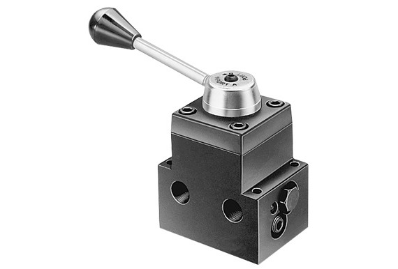
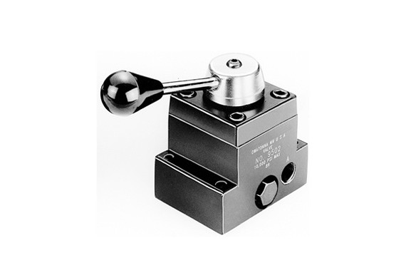
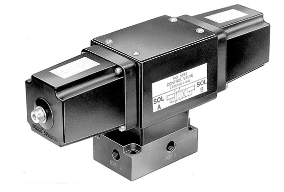
Basic valve types include manually operated, air or solenoid operated and pilot operated. Special application valves for pre-stressing and post-tensioning are also offered.
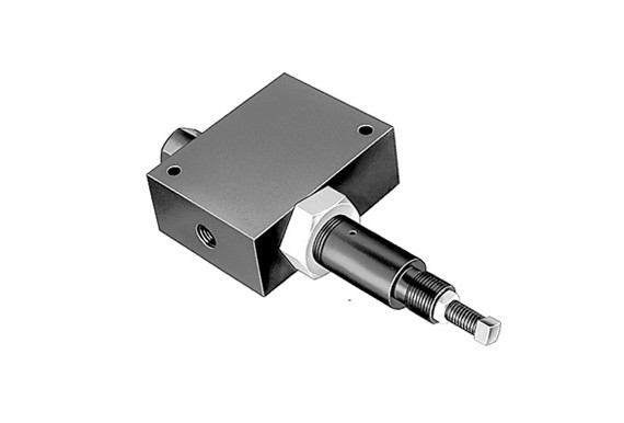
IN-LINE HYDRAULIC VALVES
Load Lowering Valve – Provides precision metering for controlled return of the cylinder pistion.
Sequence Valve – Used when a cylinder in a multiple cylinder application must advance before any other.
Pressure Reducing Valve – Permits independent pressure control to two or more clamping systems operated by a single power source.
Shut-off Valve – For fine metering of hydraulic oil. Several may be used to control multiple single-acting cylinders.
Check Valve – Permits flow of hydraulic oil in one direction only.
Pressure Relief Valve – Used at remote location in a hydraulic circuit where maximum pressure requirements are less than the setting of the basic overload valve in the pump. Protects a hydraulic system against over pressurization.
Metering Valve – Restricts surges by restricting flow to a certain level; when flow subsides, valve reopens automatically. For systems using large cylinders or extended lengths of hose.
Pressure Regulator Valve – Permits external adjustment of operating pressures at various values below the internal relief valve setting of the pump.
2-WAY, 2-POSITION
(FOR CONTROL OF SINGLE-ACTING CYLINDERS):
| POSITION 1 | CENTER POSITION | POSITION 2 |
|---|---|---|
 – Diagram") Oil goes from pump to cylinder; pressure is held from valve to cylinder when pump is shut off. |
None. |  – Diagram") Oil goes from cylinder to pump; pressure is released to reservoir when motor is turned off. |
3-WAY, 2-POSITION
(FOR CONTROL OF SINGLE-ACTING CYLINDERS):
| POSITION 1 | CENTER POSITION | POSITION 2 |
|---|---|---|
Oil goes from pump to cylinder and holds when pump is shut off. Return line to reservoir is blocked. |
None. |  – Diagram") Cylinder retracts, oil returns to reservoir. |
3-WAY, 3-POSITION
(FOR CONTROL OF SINGLE-ACTING CYLINDERS):
| POSITION 1 | CENTER POSITION | POSITION 2 |
|---|---|---|
Oil goes from pump to cylinder and holds when pump is shut off. Return line to reservoir is blocked. |
 – Diagram") Cylinder pressure is held; pump can remain running and oil returns to reservoir. |
All oil is open to reservoir through return line. |
4-WAY, 2-POSITION
(FOR CONTROL OF SINGLE OR DOUBLE-ACTING CYLINDERS):
| POSITION 1 | CENTER POSITION | POSITION 2 |
|---|---|---|
 – Diagram") Oil goes to the « extend » side of the cylinder. The oil from the « retract » side returns to reservoir. Cylinder holds with pump shut off. |
None. |  – Diagram") Oil goes to the « retract » side of the cylinder, oil from the « extend » side returns to reservoir. |
4-WAY, 3-POSITION
(FOR CONTROL OF DOUBLE-ACTING CYLINDERS):
| POSITION 1 | CENTER POSITION | POSITION 2 |
|---|---|---|
Oil goes to the « extend » side of the cylinder, oil from the « retract » side returns to reservoir. Cylinder holds with pump shut off. |
 – Diagram") Holds pressure even if pump is running. Oil from pump goes through valve, back to reservoir. |
Oil goes to « retract » side of cylinder. Oil from « extend » side returns to the reservior. |
TYPICAL CENTERS:
| TANDEM CENTER | CLOSED CENTER | OPEN CENTER |
|---|---|---|
Cylinder ports are blocked, oil from pump goes to reservoir. Used when pump remains running. Example: gasoline-driven pumps. |
 – Diagram") Generally used when running multiple valves in series from one pump. |
 – Diagram") Open Center used when holding is not a requirement, as when running two separate hydraulic tools such as cutters and crimpers. |

| Order No. | Cylinder Application * |
Operation | Valve Type | Volt | Advance/ Return |
Advance/ Hold Return |
Posi-Check® Feature | Weight (lbs.) |
|---|---|---|---|---|---|---|---|---|
| 9500 | S.A. & D.A. | Manual | 4-way, 3 Pos. Tandem Center | — | No | Yes | No | 4.2 |
| 9501 | S.A. & D.A. | Manual | 4-way, 3 Pos. Closed Center | — | No | Yes | No | 4.2 |
| 9502 | S.A. | Manual | 3-way, 3 Pos. Closed Center | — | No | Yes | Yes | 4.2 |
| 9504 | S.A. & D.A. | Manual | 3/4-way, 2 Pos. | — | Yes | Yes | No | 4.2 |
| 9506 | D.A. | Manual | 4-way, 3 Pos. Tandem Center | — | No | Yes | Yes | 5.1 |
| 9507 | D.A. | Manual | 4-way, 3 Pos. Closed Center | — | No | Yes | Yes | 5.0 |
| 9511 | S.A. & D.A. | Manual | 4-way, 3 Pos. Open Center | — | Yes | Yes | No | 4.2 |
| 9512 | D.A. | Solenoid | 4-way, 3 Pos. Tandem Center | 24 | No | Yes | Yes | 18.1 |
| 9513 | D.A. | Solenoid | 4-way, 3 Pos. Tandem Center | 115 | No | Yes | Yes | 18.1 |
| 9516 | D.A. | Solenoid | 4-way, 3 Pos. Tandem Center | 12DC | No | Yes | Yes | 18.1 |
| 9517 | S.A. | Manual | 2-way, 2 Pos. | — | No | Yes | No | 3.2 |
| 9519 | D.A. | Solenoid | 4-way, 3 Pos. Tandem Center | 230 | No | Yes | Yes | 18.1 |
| 9520 | S.A. | Manual | 4-way, 3 Pos. Tandem Center | — | No | Yes | Yes | 5.1 |
| 9522 | D.A. | Solenoid | 4-way, 3 Pos. Open Center | 230 | Yes | No | No | 15.5 |
| 9523 | S.A. | Pilot Operated Solenoid | 3-way, 2 Pos. | 230 | Yes | No | No | 8.2 |
| 9552 | S.A. & D.A. | Solenoid | 3/4-way, 2 Pos. | 230 | Yes | No | No | 14.6 |
| 9553 | S.A. | Pilot Operated Solenoid | 3-way, 2 Pos. | 24 | Yes | No | No | 8.2 |
| 9569 | S.A. | Solenoid | 3-way, 2 Pos. | 24 | No | Yes | No | 9.6 |
| 9570 | S.A. | Solenoid | 3-way, 2 Pos. | 230 | No | Yes | No | 9.6 |
| 9572 | S.A. & D.A. | Solenoid | 3/4-way, 2 Pos. | 24 | Yes | No | No | 14.6 |
| 9576 | S.A. | Manual | 3-way, 3 Pos. Metering Tandem Center | — | No | Yes | No | 8.5 |
| 9579 | S.A. | Solenoid | 3-way, 2 Pos. | 115 | No | Yes | No | 9.6 |
| 9582 | S.A. | Manual | 3-way, 2 Pos. | — | No | Yes | No | 2.5 |
| 9584 | S.A. | Manual | 3-way, 2 Pos. | — | No | Yes | No | 1.8 |
| 9589 | S.A. | Pilot Operated Solenoid | 3-way, 2 Pos. | 115 | Yes | No | No | 8.2 |
| 9590 | D.A. | Solenoid | 4-way, 3 Pos. Open Center | 115 | Yes | No | No | 15.5 |
| 9592 | S.A. & D.A. | Solenoid | 3/4-way, 2 Pos. | 115 | Yes | No | No | 14.6 |
| 9594 | S.A. & D.A. | Air | 3/4-way, 2 Pos. | — | No | Yes | Yes | 11.0 |
| 9599 | S.A. | Pilot Operated Solenoid | 3-way, 3 Pos. Tandem Center | 24 | No | Yes | Yes | 14.0 |
| 9605 | S.A. | Pilot Operated Solenoid | 3-way, 3 Pos. Tandem Center | 115 | No | Yes | Yes | 14.6 |
| 9609 | S.A. | Pilot Operated Solenoid | 3-way, 3 Pos. Tandem Center | — | No | Yes | No | 8.7 |
| 9610 | S.A. | Auto Pilot Operated | 3-way, 2 Pos. | — | Yes | No | No | 4.2 |
| 9610A | S.A. | Manual | 2/3-way, 2 Pos. | — | No | Yes | No | 4.4 |
| 9615 | D.A. | Solenoid | 4-way, 3 Pos. Open Center | 24 | Yes | No | No | 15.5 |
| 9628 | S.A. & D.A. | Manual | Post Tensioning | — | Special | No | No | 5.4 |
| 9632 | S.A. & D.A. | Manual | Post Tensioning | — | Special | No | No | 13.6 |
| * “S.A.†represents single-acting cylinders, “D.A.†represents double-acting cylinders | ||||||||
| Catalog | |