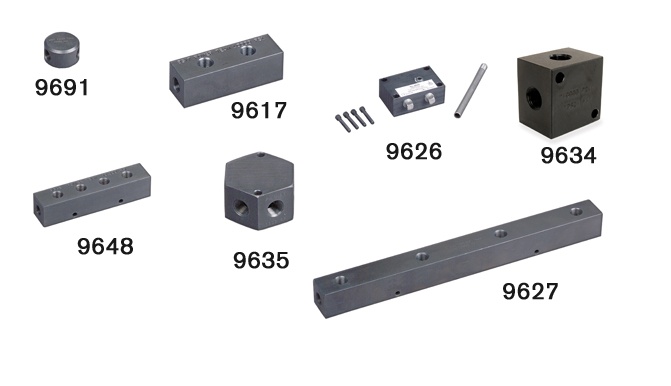

When multiple-cylinder installiation is required.
| Order No. | Description | Weight (lbs.) |
|---|---|---|
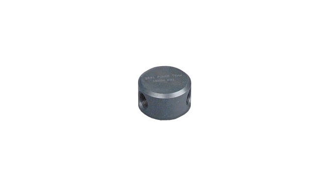
| 9691 | “Y†Manifold - Extremely useful when connecting two hydraulic cylinders to a single line. Has three 3/8″ NPTF ports. | 1.0 |
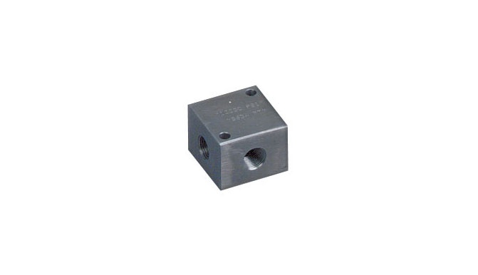
| 9634 | Manifold block - This manifold is for multiple-cylinder installations, has four 3/8″ NPTF ports and two 1/4″ mounting holes. | 1.5 |
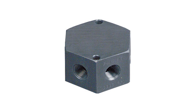
| 9635 | Manifold block – This hex-shaped manifold offers extra versatility with six 3/8″ NPTF ports and two 1/4″ mounting holes. | 2.0 |
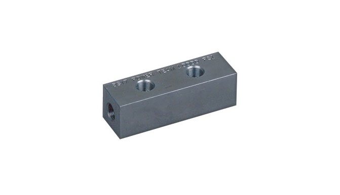
| 9617 | Manifold block - When a multiple-cylinder installation is required, this manifold is invaluable. Has six 3/8″ NPTF ports to handle larger multiple-cylinder systems. | 3.0 |
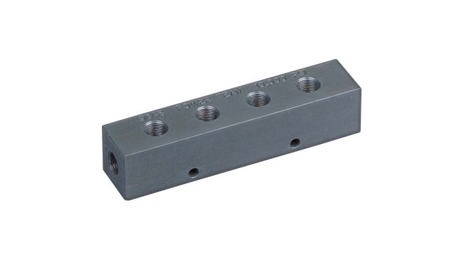
| 9648 | Manifold block – This 7″ long manifold block has seven 3/8″ NPTF ports and two 1/4″ mounting holes. | 2.7 |
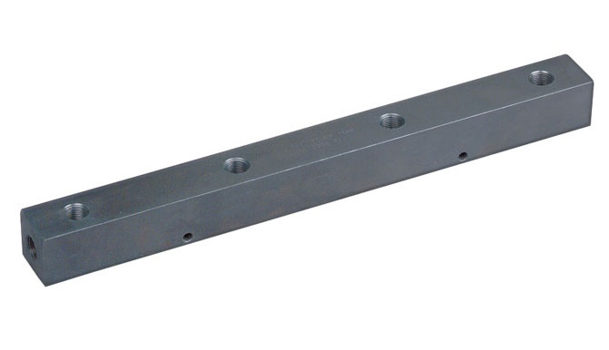
| 9627 | Manifold block - This 16″ long manifold block allows you to mount the 9575 or 9596 valves without interference. Has seven 3/8″ NPTF ports and two 1/4″ mounting holes. | 6.0 |
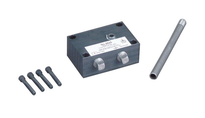
| 9626 | Pump mounted manifold block - Converts pumps with pump mounted valves for use with remote mounted valves. This manifold block is subplate mounted on the pump cover plate and provides 3/8″ NPTF pressure and return ports. Maximum recommended flow rate is 5 gpm.
Note: If used on PE30 or PG30 series pump, 1/2″ longer mounting screws are required. Order four (4) No. 11956 screws separately. |
 |
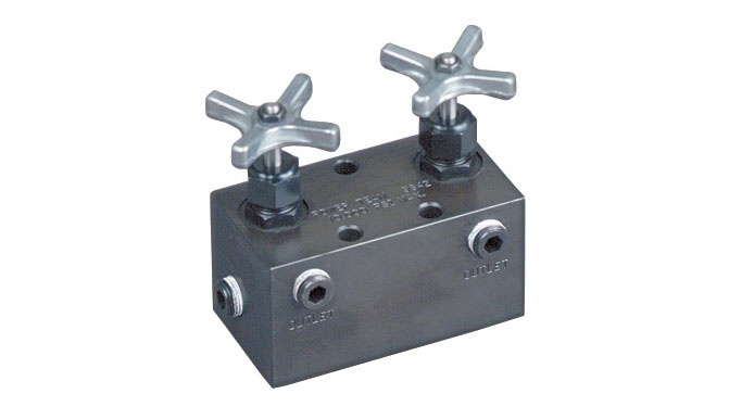
| 9642 and 9644 | Manifold blocks with Need Valves - For independent multiple-cylinder operation, feature needle valves for precise manual control. Designed for remote-mounted applications. Can be used with all Power Team pumps. | Â |
| 9642 | Manifold with two needle valves for control of two cylinders. Has four 3/8″ NPTF ports. | 8.2 |
| 9644 | Manifold with four needle valves for control of four cylinders. Has six 3/8″ NPTF ports. | 16.2 |
9642 Diagram

9644 Diagram

| Order No. | A (in.) |
B (in.) |
C (in.) |
|---|---|---|---|
| 9627 | 16 | 4 1/2 | 1 1/2 |
| 9648 | 7 | 1 1/2 | 1 1/2 |
| Catalog | |
| Parts List | |